Discussions, insights and opinions about numerical simulations, Computational Fluid Dynamics (CFD), Finite Element Analysis (FEA), Engineering Design, Software Development and everything related.
Objective: D65 is a type of horn of Diameter 65mm and mainly consists of a resonator and a diaphragm which are separated by an air column which is responsible for the functioning of the horn. The resonator of the horn is 0.6mm in thickness and attached to the diaphragm with the help of a washer. The resonator consists of three humps in its design. The functioning will be best when the frequency of the air gap and resonator match or are almost equal and this is analyzed by various FEM methods.
FEA Model-hexahedral elements-Diaphragm
Stress Contours
Methodology and Analysis: By using FEM we can easily find out the frequency of the resonator but the frequency of the air column is a fluid-solid interaction(FSI) problem. Advanced FEM algorithm was used for the air column frequency and then by iterative method the frequency of both were matched . From the analysis done, some factors which can improve the design are modifying the dimension of the washer between resonator and diaphragm, like 0.5, 0.8, 1.0 etc and modification in the thickness of the resonator. Analysis is done by using different thickness of the resonator for different dimension of the washer. Few of the results are shown in the image.
Result and Conclusion: From various analysis done it can be concluded that the dB and quality of sound depends on the natural frequency of the air column and natural frequency of the resonator. Smaller the gap the better will be the quality of sound in the particular range. Since 0.6mm is the actual thickness of the resonator which upon analysis was modified to 0.4mm so that the air column volume was increased and hence the quality of sound improved. After changing the thickness and the profile the output is found to be good i.e. 0.4mm thickness and base is up from second hump and outer side by 0.8mm. Hence the resonator design was optimized to produce maximum sound with high quality.
In real world, it is never acceptable to set fire inside iconic and large commercial buildings or facilities. But if you are working at Mechartés, you will come across buildings & facilities that are set on fire routinely to simulate real and potential fire scenarios on computers to assess their impact and methods of controlling these fires.
The destruction caused by fire in urban establishments is known to human civilization since the time in antiquity when Rome burned for six days continuously. But in modern times, fire engineering practices have reduced causalities & infrastructure damage exponentially. Today, the scope of fire safety is not only limited to extinguishing fire but covers wide variety of disciplines like early fire detection, smoke management, provision for escape facilities; even during building space & layout planning and last but definitely not least, proactive use of dynamic fire modeling to assess risks to life and property and to develop effective fire protection & evacuation strategies for scenarios that cannot be predicted by conventional wisdom.
Even with modern engineering and safety practices, the threat of accidental fire cannot be negated in modern building and industrial infrastructures. This threat brings the necessity of fire modeling to the forefront of large building and industrial facility design & development. With advances made in computer hardware performance and numerical algorithms, Computational Fluid Dynamics (CFD) software are routinely used by engineers to come up with ingenious & effective solutions to minimize damage to life and property.
Fire Dynamics Simulator (FDS) is one such CFD software actively developed by National Institute of Standards and Technology (NIST), to simulate fire driven fluid flow in situations of varying complexities. The hydrodynamic model, combustion model, thermal radiation model, sprinkler model etc, that are incorporated in FDS are continuously verified and validated by the active community of academic, scientific and professional interest group. This community effort has developed FDS into a robust and reliable software to model and simulate fire & smoke propagation inside buildings and facilities. Apart from dynamic fire modeling, numerical simulation methods are also actively used to simulate evacuation and predict indoor air quality inside buildings. Modern evacuation modeling software have reached the capability to incorporate psychological responses of human beings to fire inside enclosed spaces. With software like CONTAM, important information about exposure of occupants to airborne contaminants can be modeled and simulated for eventual risk assessment.
Modern design practices for fire safety are increasingly adopting numerical simulations to study the behavior of a fire protection system without building it. The results are accurate in general, compared to analytical model, especially when applied in complex situations. These simulations are also helping fire engineers to find unexpected phenomenon, behavior of the system and easily perform “What-If” analyses. Mechartés has been enabling our customers to address the following design & safety concerns:
What locations inside a building can be described as the “worst” location for a fire incident?
What is the minimum response time required during evacuation in a given “worst” condition?
With the proposed fire safety & evacuation methodology, what changes can reduce loss of life and property?
What is the effectiveness of smoke extraction fans and equipments?
Finally, do take out 5 minutes to view our presentation on how fire simulation services can be used to engineer your buildings and facilities for fire safety.
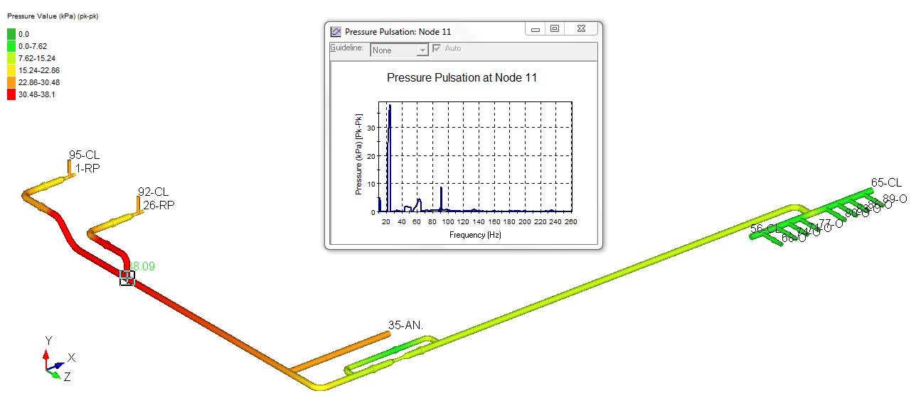
Objective: Piping systems are a central part of numerous engineering installations. A number of sources such as pumps generate vibrations which can propagate along the pipes and excite other structures. These vibrations can cause two main problems, namely mechanical fatigue and acoustical noises. Further, interaction of the dynamic flow generated by the pump plungers with acoustical resonances in piping systems can result in high pressure pulsation levels pump and piping, cavitation, excessive vibrations and failures. Moreover, higher frequency fluid borne noise can be generated from flow perturbations associated with elbows, valves or cross section changes in the pipe. This design approach in conjunction with pulsation simulation is required to couple technical analysis of piping system to ensure that the piping will have adequate supports and clamps to maintain mechanical natural frequency of major acoustical energy.
Modeling and Analysis: The first design approach involved pulsation and vibration control through the use of good piping layout and support principles, adequate suction pressure and use of pulsation control devices such as dampers, accumulators, preventers, hydraulic isolators, inhibitors, suppressors, stabilizers, acoustic filters and selected piping configurations.The acoustical simulation techniques predict the potential of cavitations and the required minimum suction to prevent cavitations, based on amplitudes of the pulsations. The results obtained from the analysis proved that the pulsation levels at the suction end were considerably reduced and the pulsation levels were found to be under API 674 standards. Based on the pulsation amplitudes at various frequencies harmonic loads acting on the pipelines were calculated. These harmonic loads were applied at respective nodes and a FEM based harmonic analysis was done to determine the natural frequency of the system and response of the system to harmonic loads arising from pressure pulsations.
Conclusion: From the analysis the pipeline was first tested for the given set of pulsation damping equipments and reciprocating pumps. It was observed that the old configuration did not provide the desired pulsation control in the system. We observed amplification in pulsation in the suction side which was much above the values accepted by API and cavitations were observed at the suction end of the plunger. To reduce the pulsation it was therefore suggested that an additional pressure dampening equipment of size 1 liter must be installed 0.55 m from the suction end of the reciprocating pump. Further the analysis done on the pipeline with the additional dampening accumulator shows considerable reduction in pressure pulsation and the pulsation amplitudes were much below the allowable limits
Objective: The objective of this project was to verify the design of a ventilation system for the basement car parking area using CFD. The specific aim is to find the optimal locations, number & configuration of the induction fans required for the ventilation of the car parking lot, for the given positions of inlets and exhaust, and given configuration of the Supply air fans & exhaust fans, such that it meets requirements of CO exposure limit set by health & safety regulations and also to check whether it meets the sufficient visibility & temperatures in case of fire.
CO PPM Without Jet fans at 1.7 m
Technical Challenge: The acceptance contaminant level criterion for parking garages is specified in ASHRAE 2007 handbook. According to ASHRAE, the main criterion for car parks is that the carbon monoxide levels should remain below a designated peak value.
CO PPM with Jet fans at 1.7 m
Engineering Solution: The mathematical modelling using CFD can be developed which would simulate the actual behavior of the system. At first the analysis was done without placing any jet fans. This provides an indication of the stagnant areas in the car park. The subsequent analysis is done with jet fans operating so as to remove the stagnant areas , to reduce the concentrations of CO and to remove smoke in case of fire.
Velocity Vectors at 1.7 m without Jet fans
Results and Conclusion:
The CO concentrations from the CFD simulations, without using induction fans has been obtained as 167.5 ppm which is higher than the safe CO limit for human beings.
After conducting CFD analysis by placing and optimizing the jet fans in the car park area, maximum CO level found to be as 27.8 ppm (33.36 mg/m3), which is with in safe CO limit for humans.
Ventilation System in the car park area has been designed optimally to reduce the CO level within the acceptable limits.